
802.11ax/HE/Wi-Fi 6 introduced the concept of content channels in the HE preamble. This is further developed into the 802.11be/EHT/Wi-Fi 7 standard. Content channels are used in the EHT MU frame format and therefore, used in most of the EHT data frames sent between stations. This blog article will explain content channels setup for DL OFDMA frame on an 80 MHz channel, and in the end the setup for 20 and 40 MHz channels.
I did a presentation on the same topic for Candela Technology Summit 2025. This video is on YouTube.
So you have two choices: click on the picture for the video or read the rest of this article

I have written several blog articles for the HE standard without mentioning about content channels because I had not read those chapters in the standard. But now I have read the 802.11be amendment and will try to explain it to you. I have used the 802.11be draft 7.0 and most of the content is from $36.3.12.8, EHT-SIG. This draft uses 35 pages to explain the EHT-SIG subfields in the EHT PPDU frame format.
Purpose of Content Channels
An OFDMA-transmission need to inform about RU/MRU allocation in the HE or EHT preamble. It is a lot of bits needed to be transferred. If those bits were transferred in “serial” form, all in the same subfield in the preamble and duplicated on all used 20 MHz channels, the preamble would be long. With content channels, different preamble information is sent on different 20 MHz preambles. and the preamble is shorter
EHT MU PPDU frame format
The EHT MU PPDU frame format looks like this:
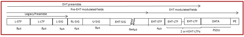
The EHT preamble are from the start of the frame to the data field, while the legacy preamble is only the first three subfields.
The pre-EHT modulated subfields use the legacy subcarrier spacing of 312.5 kHz and 3,2 µs symbol time + GI, with BPSK modulation and 1/2 encoding. The EHT-SIG can use other modulation types.
The EHT modulated subfields use the new subcarrier spacing of 78,125 kHz and 12,8 µs + GI symbol time
Preamble duplication
When we use a wider channel bandwidth in Wi-Fi we duplicate the full preamble on all used 20 MHz channels, meaning we send the same preamble information on all used 20 MHz channels to let the receivers synchronize. This is called duplicated preamble.
The Legacy Preamble
The Legacy preamble is for initial synchronization, frequency offset, channel estimation, and backward compatibility with legacy generations of Wi-Fi.
Legacy stations or other stations not correctly receiving the rest of this PPDU will use the combination of LENGTH- and RATE parameter in the legacy preamble to calculate the duration of this frame and defer transmission.
RL-SIG
RL-SIG (Repeated L-SIG) is used in HE and EHT frame formats. It is a copy of the L-SIG subfield. If HE or EHT stations see the L-SIG and RL-SIG they understand it is HE or EHT frame format. Then they do a modulus-3 calculation on the LENGTH-parameter. If the remainder is 0, it is an EHT frame. If the remainder is 1 or 2, it is one of the four HE frame formats.
U-SIG
U-SIG (Universal SIG) is common information to all EHT stations and contains information like PHY version, UL/DL, Bandwidth, BSS Color, TXOP, PPDU Type, and Puncturing information.
It also contains information on which modulation index (MCS) is used for the EHT-SIG subfield and how many symbols the EHT-SIG subfield have
EHT-SIG
It is in the EHT-SIG subfield where all the receiving stations are informed on how the channel are subdivided into RU and MRUs during the data field transmission, and which station-ID receives their data in which RU/MRU. The number of receiving stations can be very high during DL OFDMA. On a 20 MHz channel, up to 9 stations can receive their data in 26-tones RUs. And with the introduction of MRUs in EHT there are a lot of possibilities on all channel widths.
Therefore, HE and EHT use the concept of content channels. There are different content channel formats for different EHT frame types. If the U-SIG informs about DL, 80 MHz (or 20/40) bandwidth, and OFDMA the content channel format is like this (figure from IEEE 802.11be draft 7.0):

As you can see, there is a Common field and a User-Specific field in a content channel. Remember from now on, the content channel is equal to the content in the EHT-SIG subfield.
EHT-SIG content channel
The EHT-SIG content channels are of variable bit sizes depending on which bandwidth being used during the transmission and the number of receiving stations. The content is:
- First, there are 17 bits called U-SIG overflow. These are bits common to all stations for information about Spatial Reuse, GI+LTF Size, number of EHT-LTF symbols, and other things. These bits are duplicated in all preambles
- Then one or two RU Allocation-A subfields, each of 9 bits. Each RU Allocation-A subfield informs about how one 20 MHz channel is subdivided in the data field of the transmission
- Two or more user fields to inform which station-ID is receiving their information in RU/MRUs. More on this later
To understand the setup for RU Allocation-A field, I will explain this with the use of an 80 MHz channel. For an 80 MHz DL OFDMA transmission, we need two content channels and two RU Allocation-A subfields pr content channel, a total of four RU Allocation-A fields. One RU Allocation subfield pr 20 MHz data channel to inform about the allocation/subdividing for the respective 20 MHz channel. Then we put two of the RU Allocation-A subfields in content channel 1 in the preamble on the first 20 MHz channel, and the other two RU Allocation-A subfields in the other content channel in the preamble on the second 20 MHz preamble
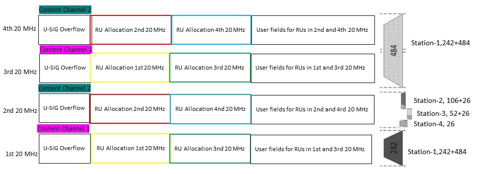
So, for an 80 MHz DL OFDMA the EHT-SIG field looks like this, together with the full EHT MU frame format:

To the left are the content channels for each 20 MHz shown, and to the right is a virtualization of the 80 MHz channel used for sending data in Resource Units (RU) and/or Multi-RU. The gap between the channels is not correct. I put in some space to make it nicer. Let us take a closer look.
The U-SIG bits is duplicated on all four preambles, for each 20 MHz channel.
In content channel 1, sent in the EHT-SIG field in the first 20 MHz preamble, we have first the RU-allocation for the first 20 MHz of the data field, marked yellow. Then we have RU-allocation for the third 20 MHz of the data fields, marked green. At last, we inform about which users or station-ID is receiving data in the same allocations.
In content channel 2, sent in the EHT-SIG field in the second 20 MHz preamble, we have first RU-allocation for the second 20 MHz of the data field, marked red. Then we have RU-allocation for the fourth 20 MHz of the data field, marked blue. At last in content channel 2, we inform about which users or stations-iD is receiving data in the same allocations.
Then is content channel 1 is duplicated to the third 20 MHz preamble, and content channel 2 is duplicated to the fourth 20 MHz preamble.
RU Allocation subfield
The RU allocation subfields are 9 bits, and the mapping between the bit value and RU/MRU pattern has to be found in the standard. For 802.11be draft 7.0, it is in table 36-34. An example, if a 20 MHz channel is subdivided in a 26-tone RU, a 52+26 tone MRU, and a 106+26 tone MRU in that frequency order, the bit pattern equals decimal 51. This table specifies all RU and MRU combinations for 20, 40, 80, 160, and 320 MHz channel width. This table also explains RU Allocation setup when RU/MRUs cover more than one 20 MHz channel
User Field
The user field is to inform which user or station-ID is receiving data in allocations informed in the RU Allocations fields.
Each user field consists of 22 bits informing of the station-ID, which MCS to be used, the number of spatial streams, whether beamforming is used, and whether BCC or LDPC coding is used.
If a receiving station is assigned a RU or MRU covering two or more 20 MHz channels, its station-ID or user field is only informed about it in the first of the affected RU Allocation subfields.
Example, DL EHT OFDMA to 4 stations in a TXOP
An example to show this better. Let us assume the AP has data in its buffer and decides to send it in an TXOP with this setup:
- to Station-id 1 in a large-size MRU, a 242+484 tone MRU, basically a 20 MHz + 40 MHz channel
- to Station-id 2 in a small-size MRU, a 26+106 tone MRU, approx 10,9 MHz of a 20 MHz channel
- to Station-id 3 in a small-size MRU, a 26+52 tone MRU, approx 6,5 MHz of a 20 MHz channel
- to Station-id 4 in a small-size RU, a 26-tone RU, approx 2 MHz of a 20 MHz channel
- The second 20 MHz channel shall be used for the small-size RU/MRUs
By looking into the standard we can find this RU/MRU setup. This figure is small snippet from different figures:
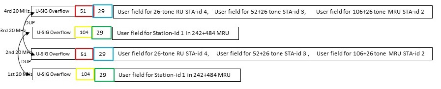
If we tie this resource allocation together with the four preambles, it looks like this:
Let us build the two content channels. In both content channels, the U-SIG overflow bits come first.
Content channel 1
The first RU Allocation field in content channel 1 informs how the first 20 MHz in the data field is allocated. To inform that this is the first part of the large size MRU of 242+488 tone with gap at the second 242-tone, we have to find the pattern of (242-tone – (gap-242-tone) – 484-tone) in the standard, in table 36-34. Since this is the first time we inform about this MRU we also need to tell that there will be one user in the user field. For this, we find the value range 104-111 and with one user the last three bits shall be 000. And that gives a decimal value of 104.
The second RU Allocation field in content channel 1 informs about how the third 20 MHz of the data fields is allocated. For the example transmission, this is the 484-tone RU that is part of the 242+484 tone MRU informed about earlier.
The standard explains decimal value 29 as : “484-tone RU; allocated, but contributes zero User fields to the User Specific field in the same EHT-SIG content channel as this RU Allocation subfield”
In the User Specific field in this content channel, we now have to inform about which user or station-ID will receive data informed in the first RU Allocation subfield, the first 20 MHz or first 242-tone. And since the same station-ID receive data in the third 20 MHz there is no need to duplicate the user or station-ID.
To summarize content channel 1
U-SIG Overflow bits + decimal 104 (explaining 242-gap-484 MRU) + decimal 29 (explaining 484-tone RU with no user info) + station-ID 1 (the 242+484 user ID). Plus some CRC and Tails
Content channel 2
The first RU Allocation field in content channel 2 informs how the second 20 MHz in the data field is allocated. In our example it is the small size RU/MRU allocations. The pattern for this 20 MHz is 26-tone RU – 52+26 tone MRU – 106+26 tone MRU. According to table 36-34 the decimal value 51 explains this pattern.
The second RU Allocation field in content channel 2 informs about how the fourth 20 MHz of the data fields is allocated. For the example transmission, this is the same 484-tone RU as explained in the second RU Allocation subfield in the content channel. Therefore, value 29 here too.
In the User Specific field in this content channel, we first have to inform about the users or station-ID that will receive data in the small-size RU/MRU of the second 20 MHz, in increasing frequency order. We don’t need to inform about which user is receiving in the fourth 20 MHz because this is explained in the first content channel.
To summarize content channel 2
U-SIG Overflow bits + decimal 51 (explaining small-size RU/MRU pattern) + 29 (explaining 484-tone RU with no user info) + station-ID 4 (the 26-tone station-ID) + station-ID 3 (the 52+26-tone station-ID) + station-ID 2 (the 106+26-tone station-ID). Plus some CRC and Tails.
So for this PPDU the EHT-SIG with the two content channels will look like this in the different 20 MHz preambles. This is without the necessary CRC, tails, and padding:
As we saw in figure 36-31 from the standard, the User Specific first have two user fields, then CRC and tail, and so on. If we set in bits numbers for the different parts, it will look like this (only the first two content channels/preambles):
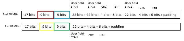
For padding, we first need to pad the first content channel to be of equal length as content channel 2, which has the most information bits. Then we need to pad both to fill the last symbol for the EHT-SIG.
In this example, there are 121 necessary bits in content channel two. If EHT-SIG is sent with MCS0 we transfer 26 bits pr symbol. Five symbols will transfer 130 bits, so both content channels need to be padded up to 130 bits.
To summarize this EHT DL OFDMA PPDU on 80 MHz
- The first part, the legacy preamble, RL-SIG and U-SIG is duplicated and sent on all four 20 MHz channels
- The EHT-SIG subfield uses two different content channels to inform the receiving stations how the data field is subdivided and which station receives their data in which allocation. For 80 MHz DL OFDMA, we have four RU Allocation A subfields where each tells allocation for a 20 MHz, a 242 tone, channel in the data field.
- Content channel 1 is sent on the first 20 MHz preamble and duplicated to the third. Content channel 2 is sent on the second 20 MHz preamble and duplicated to the fourth.
- The EHT-STF and EHT-LTF will be sent according to the content in the U-SIG Overflow bits.
- The data field is subdivided according to information in the different RU Allocation subfields and contains data for users or station-IDs as informed in the user fields.
20 and 40 MHz DL EHT OFDMA
For DL EHT OFDMA on a 40 MHz channel, we use one RU Allocation subfield in each of the two content channels, like this:

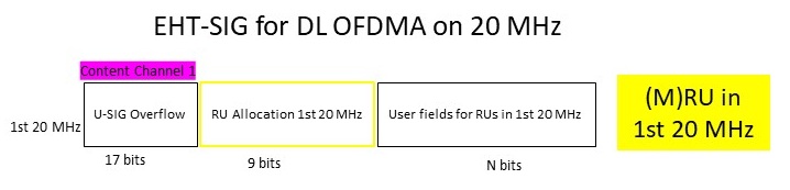
For DL EHT OFDMA on a 20 MHz channel, we use one RU Allocation subfield in one content channel, like this:
Summary
I have in this blog article tried to explain the use of content channels in EHT/802.11be/Wi-Fi 7. Everything is based on my interpretation of the 802.11be draft 7.0.
I presented it to the Candela Technology Summit in August 2025. The video is on YouTube.
In DL ODFMA, the AP needs to inform about how it has subdivided the channel and which station-ID receives their data in which allocation (RU/MRU). It is a lot of information bits to be sent, and to make the preambles as short as possible the AP uses content channels to inform about this. With this, the AP sends different information in the different preambles.
I hope this is useful for those of you who want to understand the EHT-preamble setup.
