
I started my wifi-career in 2016 with Cisco WiFi-Fundamental as self-study. While reading about Radio Resource Management (RRM), Transit Power Control (TPC) and design principles I wondered how the network and the controller (WLC) was able to set the transmit power (Tx) on each AP according to design requirement. Since then I have read through CWNP-programme, Cisco RRM white paper and some Cisco Design Guides and recommendations. Two ECSE–courses has also been completed. One instructor recommended static design and the other recommended tuning of TPC/RRM parameters
Now I am in a process of designing WiFi in one of our buildings and I’m using Ekahau Site Survey and Planner (ESS) to design the wifi-network.
So I thought why not play with ESS to give me some theoretical datapoints so that I could predict a value for RSSI_threshold for my TPC settings.
The building is 4 floors, where only second floor will get proper WiFi-design. The floor is 41 x 36m (136 x 117ft). The offices is along the outer wall, some meeting rooms in the middle and a cantine in one corner. The office walls is drywalls and set to 2dB attenuation and walls in the centre is concrete wall (12dB).
Design requirement is
- Signal strength: -67dBm/-75dBm
- Accesspoint: Cisco 2802i
- Some area don´t need coverage according to requirement, aka exclusion area
- Tx-power on access point during design phase at 14dBm or 25mW
- Designing for 5GHz, turning off enough 2,4GHz radio to have at least -67dBm from one AP at the entire floor. Eventually turn up 2,4Ghz TX-power so that only 3 2,4-radios is enabled
- Split SSID (separate SSID for 5 and 2,4GHz)
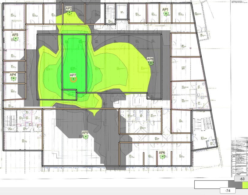
Design from ESS, showing secondary coverage and slider set to -75dBm

Cisco RRM White Paper tells that for TPCv1 the APs measures two different signal levels. RX_neighbor is how good the AP hear other APs during NDP-packet process and Tx_neighbor is how good other AP hear us. For TPCv1 calculations the Tx_neighbor level are of interest.
To find out this in ESS I turned up each APs power level at 5GHz to 20dBm or 100mW. To simplify this test lets assume 20dBm is maximum allowed power level in our regulatory domain. Then shift ESS to Signal Strength for Selected AP and turn one AP after another and simulate. I used the slider for signal strength and adjusted that so the edge between want and don´t want area or between don´t want and don´t care area touches the other APs. In this example below two access points, AP2 and AP8, hear AP7 at -63dBm and AP5 a -74dBm
Remember to change ESS visualization heights to 2,4m. Default in ESS is 1m
Simulation of how each AP is heared on the other APs (Tx_neighbor) is gathered together in this table
| Tx = 20dB / 100mW | |||||||||
| Receiver level, Tx_neighbor (dBm) | |||||||||
| AP1 | AP2 | AP3 | AP4 | AP5 | AP6 | AP7 | AP8 | ||
| Transmitter | AP1 | -91 | -65 | -65 | |||||
| AP2 | -59 | -95 | -62 | -80 | |||||
| AP3 | -59 | -49 | -82 | ||||||
| AP4 | -49 | -78 | -76 | ||||||
| AP5 | -76 | -57 | -72 | -72 | |||||
| AP6 | -65 | -57 | -90 | -74 | |||||
| AP7 | -63 | -80 | -76 | -74 | -63 | ||||
| AP8 | -64 | -80 | -73 | -75 | -64 | ||||
Cisco uses the 3´strongest Tx_neighbor in it´s TPC calculations. This values is in bold text in the table above
The formula that Cisco use to find the ideal Tx-power level on each AP is
Tx_ideal = Tx_max + (RSSI_threshold + RSSI_3´strongest AP).
Tx_ideal = 20dBm + (-70dBm + RSSI_3´strongest AP)
Tx_max is maximum allowed Tx-power in the regulatory domain. In this test that level is set to 20dBm.
If we then use this formula to find the ideal Tx-level on our access point and use the default RSSI_threshold value from Cisco WLC (-70dBm) we have those Tx-levels on our APs
| Tx_ideal (dBm) with RSSI_threshold = -70dBm | |
| AP1 | 41 |
| AP2 | 30 |
| AP3 | 32 |
| AP4 | 28 |
| AP5 | 22 |
| AP6 | 24 |
| AP7 | 24 |
| AP8 | 23 |
As we can see in this table the WLC has calculated that each AP should have a Tx-level above Tx_max, so all APs will be set to Tx_max; 20dBm or power level 1.
This does´t fit our design requirement where Tx should have been 14dBm
Cisco WLCs can configure the RSSI_threshold between -50dBm and -80dBm in the RF Profiles. Default is -70dBm
Lets us reorganise our formula to give us RSSI_threshold based on fixed Tx level at 14dBm.
RSSI_threshold = Tx_ideal – Tx_max + RSSI_3´strongest AP.
RSSI_threshold = 14dBm -20dBm+ RSSI_3´strongest AP
| RSSI_threshold for Tx = 14dBm | |
| AP1 | -97 |
| AP2 | -86 |
| AP3 | -88 |
| AP4 | -84 |
| AP5 | -78 |
| AP6 | -80 |
| AP7 | -80 |
| AP8 | -79 |
Our calculated values for RSSI_threshold is between -78dBm and -97dBm, so lets try with RSSI_threshold to -80dBm for all APs
Tx_predicted =Tx_max + (RSSI_threshold_configured + RSSI_3´strongest AP)
Tx_predicted = 20dBm + (-80dBm + RSSI_3´strongest AP)
Our Tx_predicted will then be
| Tx_predicted (dBm) | |
| AP1 | 31 |
| AP2 | 20 |
| AP3 | 22 |
| AP4 | 18 |
| AP5 | 12 |
| AP6 | 14 |
| AP7 | 14 |
| AP8 | 13 |
Now we are at least inside power levels that are useable for our APs, except AP1 and AP3. If we adjust these levels to useable power level in Cisco WLC (20/17/14/11 … dBm) we get these power level (in dBm and Cisco power level) that APs should stabilize at after a DCA restart
| dBm | Power level | |
| AP1 | 20 | 1 |
| AP2 | 20 | 1 |
| AP3 | 20 | 1 |
| AP4 | 17 or 20 | 1 or 2 |
| AP5 | 11 or 14 | 3 or 4 |
| AP6 | 14 | 3 |
| AP7 | 14 | 3 |
| AP8 | 11 or 14 | 3 or 4 |
But still only AP5, AP6, AP7 and AP7 will be at or near Tx-level from the design.
Conclusion from this very theoretical approach is that there is difficult to use the TPC algorithm and RSSI_threshold in the WLC to configure our WiFi-network according to our requirement.
Then we have three options
- Let the WLC be at default config and pray for good result
- Turn of TPC algorithm, aka static Tx levels
- Tune TPC Tx_max/max for all APs in that RF-profile/AP-group to 14dBm
Uncertainties
- Real wall attenuations don´t match the design
- Tx_max is not 20dBm in our regulatory domain
- I am way off on understanding Cisco RRM/TPC
- ESS calculations are unreliable
Next step is to install the APs and play with the configuration in the WLC and test if my theoretical approach and practical test corresponds
I´ll be back
References
Cisco RRM White Paper, 2018
