When interpreting wireless captures it is not always easy to capture the data frames because they are usually sent with complex modulation and coding schemes. The quality of the capturing NIC is also important.
But management and control frames are easier to capture because they are sent with legacy frame format (802.11b/g or 802.11a).
The BlockAcknowledge frame (BA) is the frame used by the receiving station to send back to the transmitter the status for what the receiver has received without corruption.
The last two years I have seen two different behaviors for the BA, one according to the standard and the other with a strange behavior
Let us dig into it

BlockAck Policy
After the 802.11 association, both the AP and the associated station do a negotiation between them with the Actions frames called Add Block Ack Request and Add Block Ack Response. These frames are used by the requesting station to ask the other station if they can do Block Acknowledgment , in addition to the legacy Acknowledgement. In a modern network, the requested station usually answers in response that it can do Immediate Block Ack with the Compressed BlockAck frame. It means that it will send back a BA straight after it has received a data frame, in the same TXOP.
When this negotiation is done each station sends a BlockAck Request and receives back a BlockAck. This is just a check whether the responding station can do it or not. Peter Mackenzie explains it well in this YouTube video (9-14 min).
It is named a Compressed BlockAck because the bitmap is only 8 octets (64 bits), while the uncompressed BA has a bitmap of 128 octets
The Sequence Number and the BlockAck Bitmap
When the transmitter sends a data frame it put a Sequence Number (SN) in the MAC header of each sub-MPDU. When it sends an aggregated frame each sub-MPDU gets its own Sequence Number. You can read about frame aggregation in my blog here. This Sequence Number is a 12 bits number and it goes from 0-4095. When it reaches 4095, it starts at 0 again.
The receiver builds a scoreboard or a bitmap for all the received Sequence Numbers and reports it back to the transmitter inside the BlockAck-frame. This bitmap can indicate the status of up to 64 Sequence Numbers.
The bitmap for compressed BlockAck are 64 bits or 8 octets, where each bit indicate the status for a unique Sequence Number
The normal Compressed BlockAck method
I call this method for the normal operation
For normal operations, the receiving stations do a BlockAck for the contents of the QoS Data frames in a TXOP.
This BlockAck consists of several parts where the Starting Sequence Number and the BlockAck Bitmap shows the status of the received QoS Data frames.
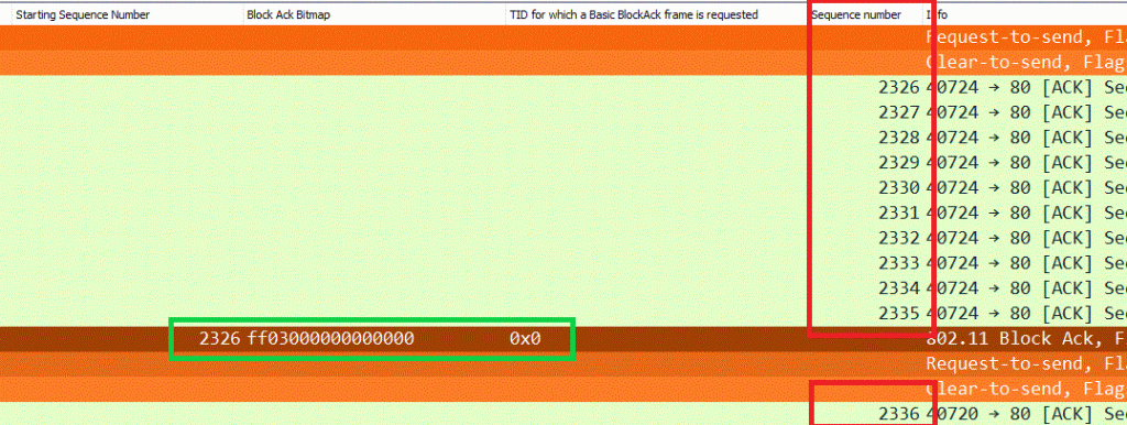
Picture 1 shows a TXOP where the transmitter sends several QoS Data sub-MPDUs with SNs 2326-2335
The receiver sends the BlockAck back with the Starting Sequence Number at 2326 (SNN=2326) which are the first SN in the TXOP and a BA Bitmap indicating how many SNs after the SSN it has received without faults. If you know how Wireshark show the bit pattern you will understand that the BA Bitmap indicates ten correct received SNs.

If we look into the same BlockAck in picture 2, we will see the Starting Sequence Number (2326), the BlockAck Bitmap, and the Bitmap Missing frame (2336). This missing frame is what the receiver expects to receive first in the next TXOP, as we can see in the first picture. This shows a TXOP without the need for retransmission

If there is a need for retransmission, the receiving station indicates it in the bitmap and in the missing frame section In picture 3 the receiving stations misses 520,521,524,555, and it has received the ones not mentioned

Picture 3: A TXOP with some missing Sequence Numbers
Summarizing the normal Compressed BlockAck
The take-out from this is that there is a tight connection between the first Sequence Number for the QoS Data frames in the TXOP and the Starting Sequence Number in the Compressed BlockAck. And the easy to understand BlockAck Bitmap
The not so normal Compressed BlockAck
Now I will explain another method of doing Compressed BlockAck. I discovered it a while ago when I started doing 802.11ax OFDMA frame analysis, but never really understand what happens. Nor have I found any documentation on it. This week I posted the challenge on the Wi-Fi Pros Slack channel and James Andrewartha told me how he had been explained it. Big thanks to James.
Further testing gave me some surprises. Let us see.
First, the normal BlockAck negotiation happens (Add Block Ack Request/Response and BlockAck Request/BA).
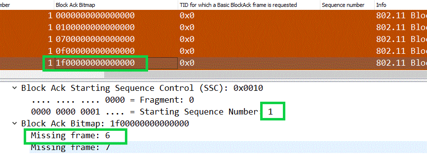
Then the receiving station starts sending Compressed BlockAck in the following TXOPs where the Starting Sequence Number stays fixed at 1, and the bitmap fills up with “1” for every correct SNs it receives. Picture 4 shows the start. The first frame is the BlockAck after BAR, then four BlockAck after receiving QoS Data SNs. You can see how the Starting Sequence number stays at 1 and the Bitmap fills up. The BlockAck in picture 4 tells us that the SSN is 1, the bitmap indicating 5, and the next SN the receiver expects to receive is SN number 6.

Further on, after the receiver receives QoS Data frames and the Sequence Number increases, the Starting Sequence Number in the BlockAck still remains at 1, but the Bitmap inceases. Picture 5 shows when the bitmaps fill up, aka for 64 successfully reception of Sequence Number. The first BlockAck in the green rectangle shows a BlockAck where the next expected Sequence number is 63, but what happens in the second frame in the green square.
Now is the BlockAck Bitmap filled with all “1” (hex all “f”), aka 64 successfully receptions of Sequence Number. From now on, when there no need for retransmission the bitmap will be all hex “f”. But the Starting Sequence Number will change/increase, you see in picture 5 that it increases til 2. In the following TXOPs the bitmap stays at all hex “f” while the Starting Sequence number increases.
In the BlockAck frame, there is no indication of what is the next expected Sequence Number

So, how to interpret this if you, as a wireless analyser, want to know which Sequence Number to expect in the next TXOP. The formula is this:
Starting Sequence Number + 64
If you want to calculate the last successfully received Sequence Number, do SSN + 63
Let us see an example
Picture 6 shows a TXOP where the QoS SNs are 1564-1567. The BlockAcks Starting Sequence number is 1504 and the bitmap is all hex “f”. There is no clear text showing what the next expected SN is in the BlockAck, which is the case with the first explained Compressed BlockAck.
So if we use the formula above for the next expected Sequence Number are: SSN + 64 -> 1504 + 64 = 1568
And the formula for the last successfully received Sequence Number are: SSN + 63 -> 1504 + 63 =1567
And as we see in the next TXOP, the first SN is 1568

If there is a need for retransmission the bitmap will indicate this. Now the bit is not all hex “f”. Picture 7 shows first a TXOP where the capturing device has captured all Sequence numbers, but the receiver fails on some of the Sequence numbers. It is possible by looking at the bitmap to manually decode which SNs the receiver fails on. The bitmap “ff ff ff ff ff ff ff c3” indicates there is four SNs missing at the receiver.
Hex “c3” after some bit swapping is binary 1100 0011, which means SN number 58, 59,60, and 61 after the SSN of 2058 is missing. And therefore, the SNs 2116-2119 are retransmitted in the next TXOP

Summarizing the NOT so normal Compressed BlockAck
The take-out from this type of Compressed BlockAck is that there is no longer a tight connection between the first QoS Data Sequence Number and the BlockAck Starting Sequence number in a TXOP.
In this type of compressed BlockAck, we need to add the Starting Sequence Number from the BA with 63 to get the last correct received SN or add with 64 to get the next expected SN in the next TXOP when the BAs bitmap is all hex “f”.
For the NIC and its driver, this is not a problem, but for the wireless analyser it gives some challenges
Why and when?
There are some questions regarding what I have explained in this blog.
- I have not found anything in all the pcaps I have tested on how this is negotiated. The Add Block Ack Request/Responses is equal regardless of which type of Compressed BlockAack been used
- It might be a difference whether the BAR/BA is been used after the above Actions frames
- Different TID (traffic indicator or access category) can use different BA policies on the same connection
- It changes on all the tested clients I have tested, both against a Cisco C9115 (WiFi6 AP) and a Cisco 2802i (WiFi5 AP). Those AP are on separate networks
Does it matter which type been used?
I have not considered what the pros and cons between those two types are, and I don’t know. Maybe there are some research papers online describing and arguments for one or the other.
For me, I’m surprised of how common the “not so normal” Compressed BlockAck is on the equipment I have tested.
I have earlier observed it on my Jetson Nano in my test lab, but it also happens on my Samsung S10. And on both Cisco 2802and 9115 AP.
When this first happened in the WiFi world, I don’t know either
Summarizing
I have in this blog article described two types of Compressed BlockAck
- The “normal” type of Compressed BlockAck
It is a tight connection between the first QoS Sequence Number and the Compressed BlockAck Starting Sequence Number in a TXOP. And the BlockAck bitmap shows in Wireshark in clear text which Starting Sequence number are missing and which Sequence Number the receiver expects first in the next TXOP. - The “not so normal” type of Compressed BlockAck
The Compressed BlockAck Starting Sequence Number in each TXOP is much lower than the QoS Sequence Number in the same TXOP and to find out which Sequence Number to expect in the next TXOP you must add the Starting Sequence number with 64 - Both types have the functionality to process retransmissions on selected Sequence Numbers
- I have not found any difference in how these two different methods are negotiated between the stations
- Both methods can be used on different TIDs (access category) between the same stations
- I have not found any documentation for the “not so normal” Compressed BlockAck
I want to send a big thank you to James Andrewartha (jandrewartha on Slack) who told me how to interpret it
Pcap and Wireshark-filter
The attached pcap (zip-file) is a Jetson Nano that associates to a Cisco C9115AP, on a open WLAN. It is the pcap I used to write this blog
A very useful filter in Wireshark to display only Action frames, BlockAck Request and BlockAck is:
wlan.fc.type_subtype==13 or wlan.fc.type_subtype==24 or wlan.fc.type_subtype==25
Please, comments are welcome

Great info – was looking for a clear concise write-up on this!
LikeLike
Thank you. Not easy to find any other documentation for this
LikeLike
[…] I have written a blog article where I describe the two different BlockAck Bitmap types, look here […]
LikeLike